This is a brief guide of how to construct a Part Number for our Comfit Monoflange Valves. The first thing to note is the structure of the code, as it will provide insights into the variables included in the product specifications. The primary structure of a Monoflange Code is compound for the following segments:
Brand Reference
Construction
Inlet Connection
Outlet Connection
Type of Valve
Material
Drain Connection
Packing
Now, let’s review each segments to learn more about the different options associated with them.
Depending on the specific application, you can determine the construction of the Monoflange and the sequence in which the valves are arranged. For example, the sequence might be: first valve (isolation), second valve (bleed), and third valve (isolation).
After deciding on the construction type, the next step is to specify the inlet connection, which consists of three variables: Flange Size, Flange Face, and Flange Class. Two main flange face finishes are available: Raised Face (RF) and Ring Joint (RTJ). The ANSI Class Rating of the valve indicates its pressure-temperature rating, with each class designating a series of specific pressure and temperature combinations. For example, a Class 300 valve can withstand up to 740 psig at 100°F.
For the outlet connection, you’ll need to choose both the connection size and type. A breakdown of the available options is provided in the chart below.
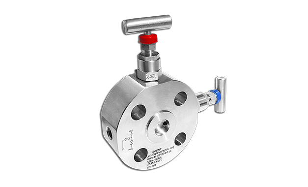
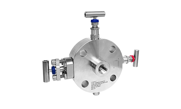
All valves incorporated into the monoflange are categorized as Instrument Needle Valves. Still, there are different types to choose from, such as the Screwed Bonnet Needle Valve, Anti-Tampered Bonnet Needle Valve, and OS&Y Needle Valve. We can see below two examples of different configurations.
Single Bock and Bleed Monoflange
Double Block and Bleed Monoflange (including OS&Y Needle Valve)
In terms of material, while the standard is 316 Stainless Steel (in which case no additional segment code is needed for the part number), other materials can be specified based on application requirements. These include, but are not limited to, 316L, 316/316L, 304, 304L, Carbon Steel, P/F321, SS347, P/F11, P/F22, P/F5, A105N, and P/F91.
Lastly, the drain connection—typically 1/4″ NPTF by default—can be customized in terms of connection size and type. Refer to the table below for other available options. Additionally, you’ll need to specify the packing material, choosing between PTFE and Grafoil.
After studying all the components of Monoflange Valves, let’s practice constructing the Comfit part number. This exercise will make it easier to understand the process and the different segments involved:
Suppose we need a 316 Stainless Steel Monoflange with the following specifications:
1. Double block and bleed, with the first isolation valve being an OS&Y type, the second isolation valve being a Screwed Bonnet Needle Valve, and the third bleed valve being a Screwed Bonnet Needle Valve. 2. The process Connection (inlet) is 1″ in size, with a raised face and a 300# class. 3. The Instrument Connection (outlet) is 1/2″ NPTF. 4. The Drain Connection is 1/2″ NPTF. 5. The packing material is Grafoil.
Based on our explanation and the table bellow, the code will be:
CIMFV-IIB-16RF300-8NF-OSS-D8-P1
Here is a detailed table of the different variables and how to construct the part Number.
You can now practice constructing a Comfit Monoflange Valve Code. If you need assistance or have any questions please do not hesitate to contact us at support@comfit-usa.com.